top of page

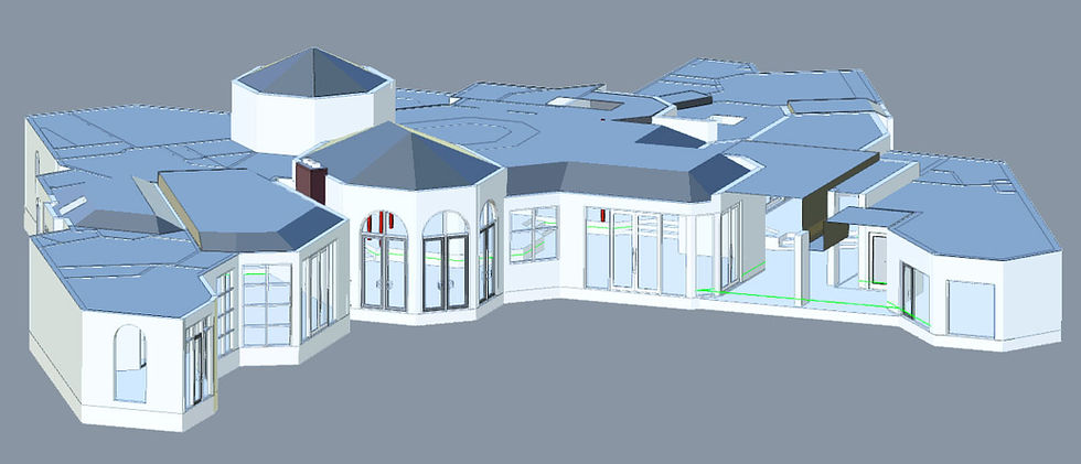
We laser scanned the master suite of a 116' Azimut megayacht at a boatyard in Ft. Lauderdale, Florida. Now, the multi-national interior team is working with one master set of measurements. in both metric and imperial formats.


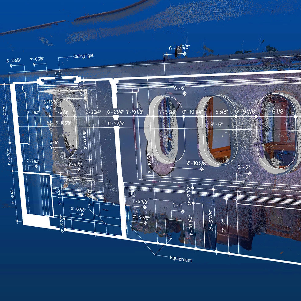
Scanning was complete in a few hours and final docs were sent less than a week later. Every slope and curve is represented with ±3mm accuracy in these as-built materials:


  • Floor plan

  • Ceiling plan

  • Interior sections/elevations

  • 3D Revit/Sketchup/IFC model

  • 3D Point cloud data


Here's a short video showing some of what we delivered:

The 35m Azimut with odd angles, curved walls and tight spaces all work against a designer's job of maximizing living space. Electric, plumbing and engineering challenges can now be solved on a computer, prior to install. Doing this all in advance helps satisfy a client who expects to have it all done quickly, without mistakes.


Once the interior designer has redesigned using the 3d Revit file, the owner can "tour" the space using 3d googles. This type of approval leaves little surprise later on while streamlining the process.


Yacht laser scanning as-built measurement documentation

interior yacht section
Interior section/elevation shown against the exterior hull.

hull radius drafted 3d scan revit
Hull radius and other measurements taken from our 3d scan and drafted as an interior section.

If our marine architecture 3d scanning services can make your job easier, please visit http://c2a.studio/bim or call our Florida studio at 1.561.866.4407.

A diverse team employs 3d modeling to enable cross continental collaboration.

Miami Beach condominium renovation project needed highly accurate floor plans and Revit model from our 3d scans.

We received a call inquiring if our 3d scanners could capture accurate measurements for an architect in Europe. They wanted as-built floor plans in metric units and a 3d Revit model so the architect could get started on a redesign without having to fly to Miami.


They called us because the original developer's 1995 floor plan had a few measurements, rounded to the nearest foot. While great for imagining a renovation, this "schematic" information is not reliable for actually getting the job done. Since starting in this business at the end of 2017, we've discovered that most floor plans are incorrect (unless a 3d scanner was used to document a project after it was built, assuming no renovations were made).

Master bathroom, window and balcony with slope measurement.

PLANS FROM 3D SCANS


The amount of information we are able to gather today is enormous. Curved walls, sloped floors, sagging ceilings and other details are now exposed for everyone to see. Our equipment is highly accurate to +/-3mm or 1/8".


If our plans were to include all of the data captured in a scan, they would be impossible to read. So by default, we include measurements that an architect might want in order to decide which walls to remove, which rooms to expand and ceilings to heighten. Varied wall thicknesses show which ones might be load bearing. In the detail below, note the increasing slope on the balcony outside the master bedroom (up to 7cm or 2.75") to allow rainwater to drain away from the sliding glass door.


Our 3D scanning allows output of exact measurements in either metric or imperial units. This helps suppliers in Indonesia working with architects in Germany can coordinate with clients in Miami Beach without fear of someone miscalculating a conversion from inches to centimeters. Even in the U.S., many contractors and subcontractors are from metric countries so democratizing measurements works locally too.


Condominium projects present special challenges with making all equipment easily accessible (while hiding it at the same time), managing noise by soundproofing surfaces and at the same time, maximizing living space. This is only possible with accurate as-built measurements.


WINDOWS, DOORS AND MORE WINDOWS


Luxury oceanfront condominiums generally have a lot of windows and this project was no exception. With three bedrooms and other areas in a 1,900-sqft space, there are also a lot of doors. Our scans picked up all of them and inventoried each one inside the 3d Revit model.


How many different sizes of window openings do you have? How thick are the frames? What are the dimensions and thickness of each pane of glass?

How about doors? How many are glass? How many are wood? Are they all the same size and thickness? How many sliders are salvageable and how many do we have to replace?


3d Revit model with window and door inventory and measurements.

With a complete as-built window and door schedule, you minimize the chance of human error in estimating, manufacturing or installation.


Is there anyone in the highly competitive window and door industry still working with hand measurements? What used to take days and weeks of labor now takes minutes and hours with 3d modeling.

3d model used to measure windows.

Our raw scan data was used as a basis for building our 3d building information model (BIM) in Autodesk Revit. The RVT file was also output as an IFC, allowing for import into various other software programs like Sketchup, BIMx and others.


This condo project was scanned in a couple of hours and once that happens, there is no need to ever go back to the site until it's time to actually install. The 3D model can exist on a cell phone so there's no need to have blueprint tubes rolling around the back of your truck.


Any general contractor can tell you that renovating a high-end condominium is like a high stakes ballet dance. Access to the unit is strictly controlled, neighbors are only feet away, ready to film and share perceived violations with the board. Spaces are tight, requiring precision carpentry, rerouting electrical and plumbing has limitations unlike in a single family home. Your ability to navigate all of the above will determine if you are able to make a profit at the end of the job.


If we can help answer questions about how to get 3d scans, CAD/BIM files or precision floor plans into your workflow, please visit http://c2a.studio/bim or call 561.866.4407.


Multiple angles with odd shaped rooms and a split level floor plan.
Multiple angles with odd shaped rooms and a split level floor plan. The front door faces due north but the rest of the angles are in all directions.

Boca Raton, Florida must have some of the most difficult to measure architecture on the planet.


The building boom in the early 1980s produced extreme layouts with odd-shaped rooms, obtuse angles next to acute angles and multiple split level floors with semi-matching split-level ceilings. Some of these mansions are 10,000 square feet or more so the rooms, angles and geometry seem to go on forever.

Case in point is this 6,000-sqft specimen of "Boca-tecture" where the only true rectangle is a small atrium near the lower left of the large floor plan above.


An interior like this would be impossible to accurately measure by hand and even if the original blueprints are available, you can be sure this home was built with some variances in execution which makes those plans inaccurate. "As-built" plans must accurately document the exact current structural specs.


This is why we were hired by a contractor to scan and provide as-built floor plans, side elevations and an accurate BIM/CAD Revit file. We began with our 3d LiDAR scanner and created a point cloud with billions of highly accurate measurements.

Building Information Model (BIM) built in Revit.
Building Information Model (BIM) built in AutoDesk Revit.

After a few hours of scanning, our point cloud became the basis for our BIM (Building Information Model) which we completed in AutoDesk Revit. Since the BIM is literally built around the point cloud, we are able to maintain the accuracy of the measurements (down to 1/8" or 3mm of actual).


While building the living room portion of the model, we noticed a few anomalies in the beams of the vaulted ceiling. The ceiling looked symmetrical but our scans revealed variances in the length of the beams. Below left are our accurate BIM measurements of the beams and on the right is a photo of the living room.

On the left is our BIM showing variances in beam length and on the right is a photograph of the interior of the living room.
On the left is our BIM showing variances in beam length and on the right is a photograph of the interior of the living room. This is most likely caused by the carpenters on install, settling of the wood over time or a combination of both.

We were then able to measure all of the beams including the tallest in the foyer which measured exactly 20.6' from the floor. In the cross section below, you can also see the elevations within the residence. Since portions of the drywall had been removed, our scanners were able to pick up the red load-bearing beams in the foyer (which we indicated as red on the BIM).

Measuring the interior height of the foyer.
Measuring the interior height of the foyer ceiling. We can also see the distance between the front door and the height of the foyer is 12.9'.

With the walls, floors and ceiling layers off, we can reveal only windows, doors, chimney and red load-bearing beams in the foyer and kitchen.
With the walls, floors and ceiling layers off, we can reveal only windows, doors, chimney and red load-bearing beams in the foyer and kitchen. This allows us to take inventory of each type of material and size of component.

Measuring vaulted ceilings with the BIM.

Having the ability to turn on/off certain layers of walls, windows, ceilings and other items within the BIM helps isolate areas for measurement, inventory, estimating and other tasks.


The BIM is then sent to various project stakeholders so they can all work from the same set of official measurements throughout the project.


Aside from the BIM and floor plans, the deliverables also included various custom "sliced" elevations including all measurements.

All of the above deliverables were captured in a few hours of scanning while measuring a project like this would have taken many days, only to end up with inaccurate data and most likely, costly changes during construction.


Side elevations of a split-level Boca Raton, Florida residence.

If you would like to discuss how 3d scanning can help with your project, please visit http://c2a.studio/bim or call us at 1.561.866.4407.


© 1998-2020 C2A STUDIO LLC

All Rights Reserved.

bottom of page